Deutsch
MINImill CAD CAM
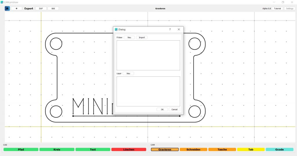
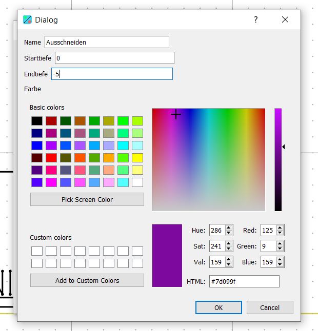
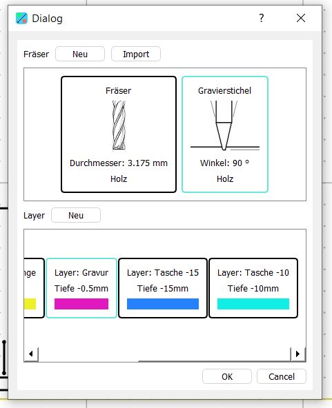
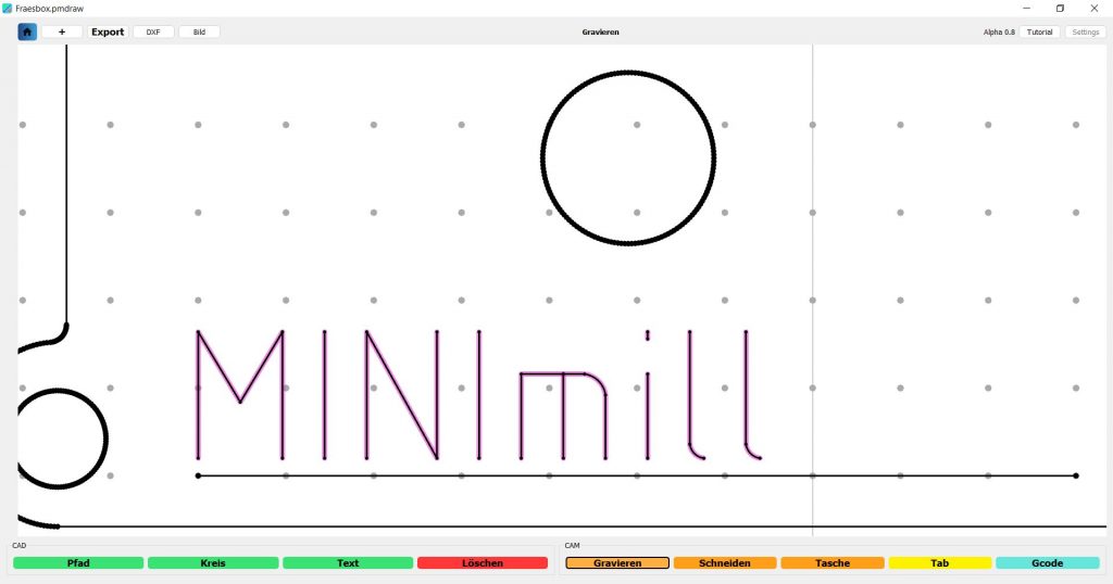
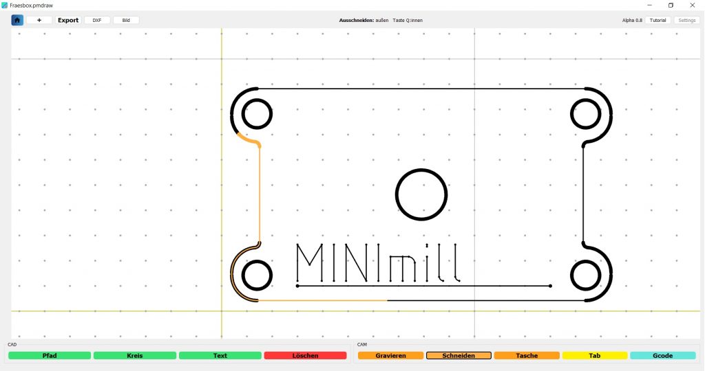
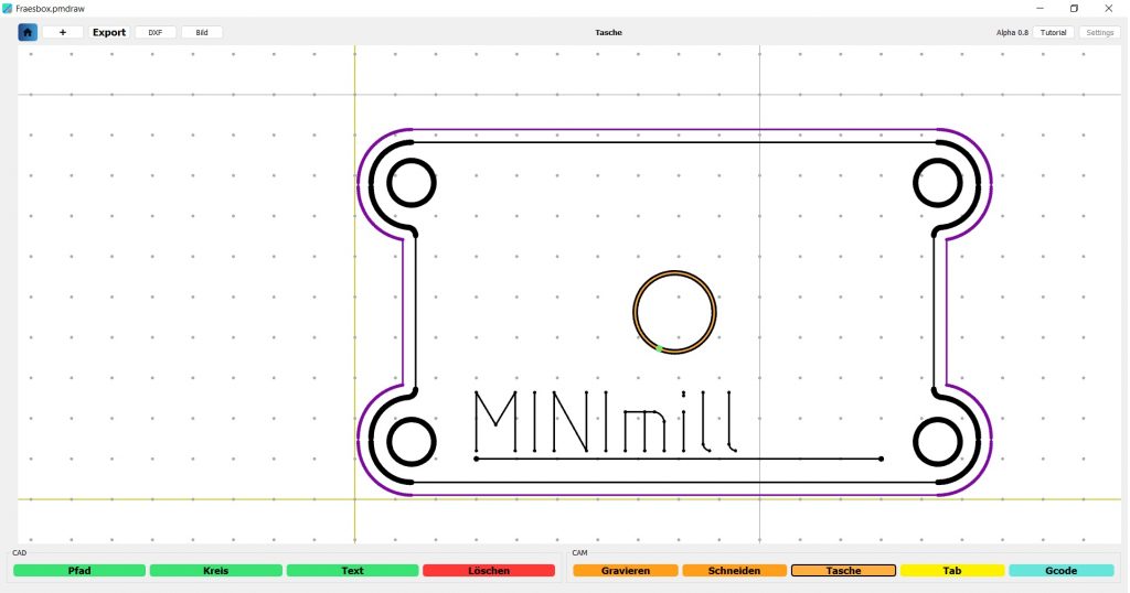
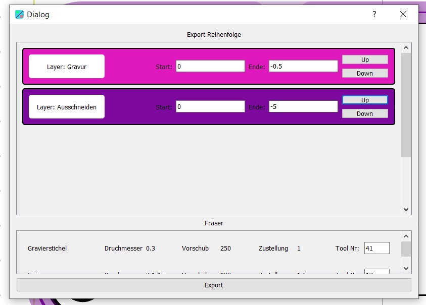
With the MINImill drawing module, you can mill out geometries, mill pockets and engrave.
The created GCODE is GRBL and DIN ISO compatible. The GCODE should be compatible with almost all GCODE senders and programs.
Please refer to the first two CAD CAM Wiki points for the basic operating and control functions.
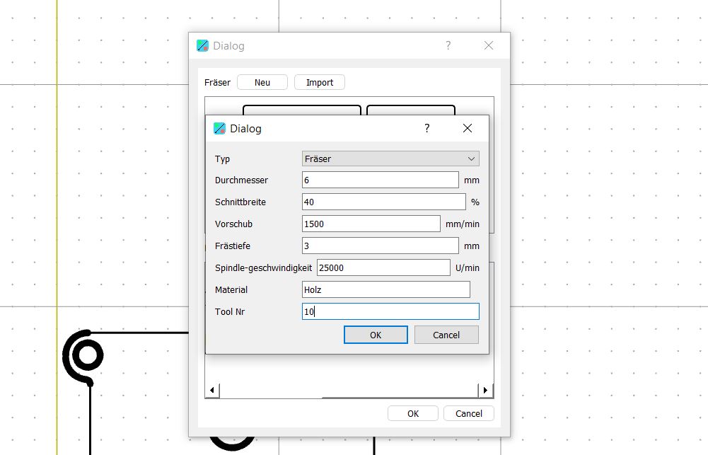
Please activate tool changer in the software before milling the GCODE as the command M6 for tool change is otherwise not recognised.